These rods are frequently used to install concrete foundations and column bases, as well as machine bases. These rods transmit the load due to tensile and shear forces from the structure to the foundations. The important point is that load capacity should not depend on the size of the rods or the type of steel.
Even if it is made of strong steel, the rod will still fail if there is cracking in the concrete, inadequate embedment, or proximity to the edge.
1. How Much Load Can Galvanized Anchor Rods Support in Concrete?
There is no standard loading capacity for galvanized anchor rods. It depends on the forces acting, material behavior, anchorage design, and concrete condition.
1.1 What Types of Loads Act on Anchor Rods?
Tension
In other words, tensile forces will act around the rod’s axis, which will stretch it away from the concrete structure. Overturning moment at the bottom of a steel column, for instance, could put the anchor on one side of the base plate under great tensile force.
Shear
Shear loads develop on the rod, usually caused by lateral loads or by moving equipment. The anchors can be subjected to tension and shearing forces simultaneously. The loads should be analyzed according to the interaction provisions of the appropriate code rather than individually verifying each one.
1.2 How Is the Tensile Capacity of Anchor Rods Calculated?
Steel yield capacity can be estimated approximately by: Ny = As × Fy
Where:
Ny: Nominal steel yield force (N)
As: Effective steel cross-sectional area (mm²)
Fy: Steel yield strength (MPa)
Consider a rod with an effective area of 245 mm² and a yield strength of 379 MPa.
Ny = 245 × 379 = 92,855 N
The calculated steel yield force is approximately 92.9 kN.
| Parameter | Example Value |
| Effective steel area | 245 mm² |
| Steel yield strength | 379 MPa |
| Calculated steel yield force | 92.9 kN |
| Design tensile capacity in concrete | Requires separate verification |
This formula is applicable only for steel yielding. This is not equivalent to the permissible working load of the anchor or its tensile strength as per ACI 318.
Calculation of concrete breakout, pullout, steel failure, and their respective factors should also be taken into consideration.
1.3 What Failure Modes Limit Anchor Rod Capacity?
Several failure mechanisms can control the strength of a concrete anchorage system.
| Failure Mode | Description | Key Factors |
| Steel tensile failure | Rod fractures under tension | Steel strength, effective area |
| Concrete breakout | A section of concrete separates around the anchor | Embedment depth, concrete strength |
| Pullout failure | Anchor loses resistance at its embedded end | Anchorage configuration |
| Steel shear failure | Rod fractures under lateral loading | Steel strength, cross-sectional area |
| Concrete edge breakout | Concrete fractures near an edge under shear | Edge distance, load direction |
Even for a high-strength steel bar, there might be some limitation in strength if it is installed close to a concrete margin. This is why engineers have to figure out the dominant failure mechanism.
2. What Factors Affect the Load Capacity of Galvanized Anchor Rods?
Rod dimensions, concrete properties, and installation conditions all influence the load capacity of galvanized anchor rods.
2.1 How Do Rod Diameter and Steel Grade Affect Capacity?
An increase in the effective steel area is expected to enhance the tensile capacity of the bolted connections, where the strength of the material does not change. For instance, if the effective area increases from 245 mm² to 353 mm² at a yield strength of 379 MPa, then the result is: 353 x 379 = 133,787 N ≈ 133.8 kN
This implies that the yield capacity of the steel will be increased by 44%. However, this does not imply that the anchorage capacity of the concrete will also be increased by the same percentage. The grade of steel is also another important consideration to take into account. The yield strength of the steel should have a minimum of 36, 55, and 105 ksi for grade 36, 55, and 105, respectively.
2.2 How Do Concrete Strength, Embedment Depth, and Edge Distance Affect Capacity?
Concrete Strength
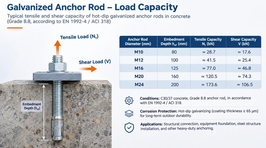
The compressive strength of concrete, denoted by f’c, usually falls between 25 and 40 MPa for various structural applications. Increased strength may enhance the ability of the concrete to withstand certain types of failure, although it is dependent on the anchorage configuration.
Embedment Depth
Embedment depth becomes important in terms of how loads are transferred to concrete. Increased embedment can increase tensile resistance for some anchoring systems, although not all of them.
Edge Distance and Spacing
Anchor bolts placed near concrete edges might face less breakout resistance. The areas of failure of closely spaced anchor bolts might overlap; hence, their capacities cannot be combined.
Cracked Concrete
Cracked and uncracked concrete may have different responses to loads applied through anchors. The design process should consider the actual state of the structure.
2.3 How Do Anchor Type and Installation Conditions Affect Capacity?
Different anchoring systems transfer loads through different mechanisms.
Cast-in-Place Anchor Rods
These are located before the placement of concrete and transmit loads either through headed ends or embedments, or via any other system of design. Their effectiveness is dependent upon the embedment shape and concrete state.
Post-Installed Anchors
Embedded in concrete, these anchors may depend on mechanical expansion, undercutting, or adhesion. The size of the holes, cleaning, and installation are factors that directly influence their effectiveness.
Self-Drilling Ground Anchors
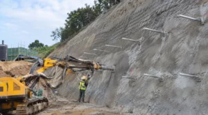
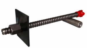
These devices use hollow screw rods for drilling and grouting through soil or rock formations. These devices have a unique method of load transfer, unlike conventional concrete foundation anchors.
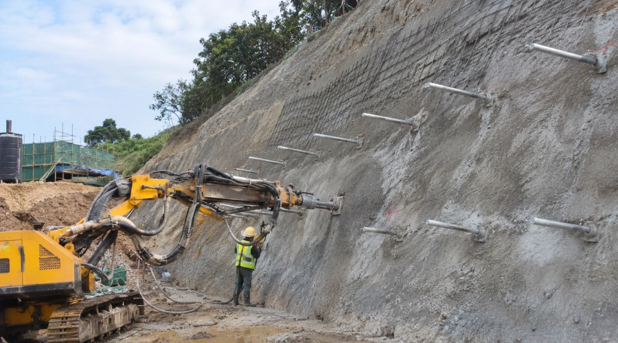
An example of such an anchoring system would be the HDG Coating Self-drilling Anchor Rods of ONTONBOLT. The hot-dip galvanized rods are used for slope stabilization, retaining walls, and other similar ground reinforcement works. They rely on the strength of the rod, couplers, grout, and surrounding ground, unlike concrete anchors.
The concrete anchorage may be designed based on the ACI 318 Chapter 17 guidelines. Engineers need to take into account the effects of combined tension and shear forces, installation quality, and the field tests required. Hot-dip galvanization offers protection from corrosion without increasing the strength of steel or anchorage.
Conclusion
The design of a galvanized anchor rod in concrete depends on many variables such as the strength of steel, the area of steel, concrete parameters, depth of embedding, and applied loads. Calculations related to the yield point of steel offer valuable initial data but do not determine allowable loads. A thorough analysis needs to include possible failure states of concrete, composite loads, and installation conditions. Proper selection of design methods is a key factor.
0